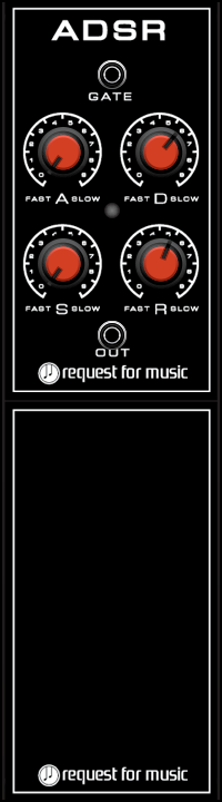

ADSR- module
Attack, Decay, Sustain and Release set the envelope, the way the sound behaves over time. A, D and R can be set between 10 ms and 20 seconds. The lower the A, D and R values are, the shorter the sound.
Sustain is set from 0% to 100%. The sustain stage is reached after Decay.
Sound will stay at the level of sustain until you release your key.
You need to input a gate signal at the input and on the bottom the Envelope signal will be returned.
Use the Envelope to drive a VCF to change sound, or to drive a VCA, to shape the volume.
Click in the bottom half of the module to place notes.
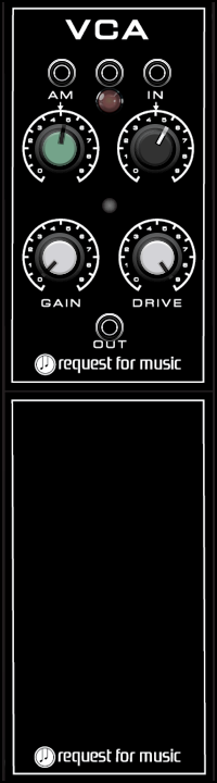
VCA-module
The VCA (Voltage Controlled Amplifier) is used to set levels for signals connected to ES (External Signal or INput)
Connect your signal to the ES input and use the GAIN knob to set the output level.
When an Envelope is connected to the input above the led-switch and LED is ON, the connected ADSR sets the level.
An LFO connected to the AM input can make for an tremolo effect – use the knob to set the level.
Click in the bottom half of the module to place notes.
VCO-module
The Voltage Controlled Oscillator is a soundsource, capable of creating sine- triangle-, square- satooth- or spaced sawtooth waves.
All waves have their own timbre and can even be combined to create unknown waves shapes.
A pitch Control Voltage from a keyboard should be connected to the EXT input to let the Oscillator follow your keyboard. The LED switch needs to be ON to make that work.
To set the basic frequency of the oscillator you use the FINE and COARSE knobs.
When a signal is copnnected to the left FM input, the FM knob sets Frequency Modulation for the VCO.
When a signal is connected to the right PWM input, the PWM knob sets the level of Pulse Width Modulation.
A square wave needs to switched on to hear that effect.
The Pulse Width of a square wave can be set to a basic percentage using the PW knob.
The Out knob finally defines the overall level of the Oscillators’ output signal.
Oh… not to forget – on top there’s an input added to SYNC the oscillator to an external oscillator resulting in very specific sounds as well.
Set the ‘following’ VCO, the one where you add a SYNC signal to, to a higher frequency than the ‘leading’ VCO that you get the signal from.
Also think of frequency modulating the following VCO. Especially using an ADSR to FM this, can result in sort of JMJs Laser-like sounds.
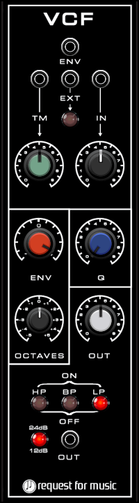
VCF-module
The Voltage Controlled Filter contains highpass-, bandpass- and lowpass 24 dB filters to shape your sound.
The filters can be combined if needed.
The cutoff frequency can be set with the OCTAVES knob. The resonance is set using the Q-knob while the OUT knob sets the overall output level of the signal connected to the bottom output.
When a signal (for instance ADSR envelope is connected to the top ENV input, the ENV knob sets the amount of effect that has on the filter.
The ENV knob goes from -1 to +1. When set to the center (0) there will be no audible effect.
Any signal to be filtered should be input into the right IN input.
The input level is set using the IN knob.
To modulate the filter connect a signal (for instance LFO) to the TM input and set the desired level using the TM knob.
Connect any signal to the EXT input to drive or modulate the filter cutoff frequency in any other desired way.
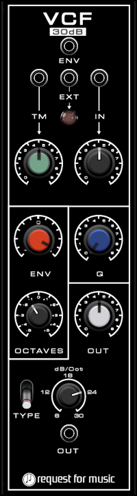
VCF30-module
This module contains three lowpass ladder filters to shape your sound.
The filters can be set to 6, 12, 18, 24 or 30 dB by turning the knob.
switch goes through the different types, having their own characteristics.
The cutoff frequency can be set with the OCTAVES knob. The resonance is set using the Q-knob while the OUT knob sets the overall output level of the signal connected to the bottom output.
When a signal (for instance ADSR envelope is connected to the top ENV input, the ENV knob sets the amount of effect that has on the filter.
The ENV knob goes from -1 to +1. When set to the center (0) there will be no audible effect.
Any signal to be filtered should be input into the right IN input.
The input level is set using the IN knob.
To modulate the filter connect a signal (for instance LFO) to the TM input and set the desired level using the TM knob.
Connect any signal to the EXT input to drive or modulate the filter cutoff frequency in any other desired way.
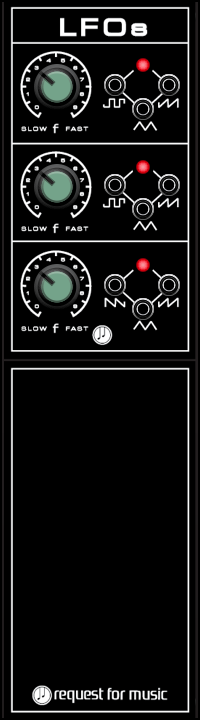
LFO-module
A Low Frequency Oscillator is a multi purpose signal source, used to modulate for instance an oscillator’s pitch to create vibrato; a filter’s cutoff frequency to generate filter sweeps, create tremolo effects by modulating AM on a VCA or many other things you can think of.
The LFO has three of those oscillators in one module.
Every LFO section has one speed knob, but you can use all three outputs of that section simultaneously.
The top and middle LFO have square-, triangle- and sawtooth waves.
The bottom LFO has sawtooth-, ramp- and triangle waves available.
The bottom part of the module can be clicked to enter notes.
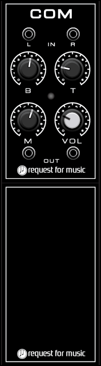
COM-module
The COM-module is sort of an end-of-the-line module.
It contains stereo in- and outputs, bass, middle and treble settings affecting the input signals and a master VOLume knob to set the outputlevel.
Click in the bottom half of the module to place notes.
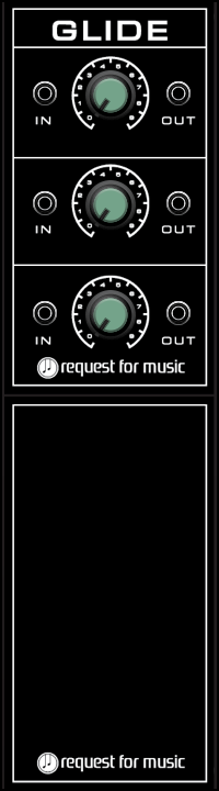
GLIDE-module
The glide module(also called portamento) is an absolute must for synthesizers to be able to make the PITCH signal from the main interface glide to the next pressed key. It smoothes out the voltage from one value to the next.
The knob sets the value for any of the three glide sections that are available in the module.
So connect your PITCH output to the input of any of the sections and take an output and connect to an EXT input of a VCO to make that VCO glide.
You can also use the GLIDE module so smoothen LFO signals or SEQUENCER pitch or even gate signals.
Click in the bottom half of the module to place notes.
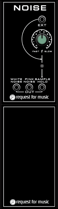
NOISE-module
A noise- module is also a very often used module in synthesizer, with outputs for WHITE- and PINK noise and SAMPLE & HOLD.
White noise can be used to create gusts of wind snare drums.
Pink noise has a slightly ‘warmer’ noise sound that you can use for other effects.
Sample & hold (S&H) takes a sample of the noise and sends that through its output. The frequency for taking such a sample is set with the knob.
However, when you for instance send a gate to the top input, you decide when to take a sample – that gate could also be sent from a sequencer, so that the random pitch would be in sync with a sequencers’ speed.
S&H creates random voltages that can be used to create pitch patterns when connected to the EXT input of a VCO, or make a filters’ cutoff frequency change randomly based on the S&H output, when connected to either ENV or TM inputs of the VCF – the TM input has a knob to dial in the strength of that effect. Especially when used with higher Q (resonance) settings, this can sound quite effectively.
Click in the bottom half of the module to place notes.
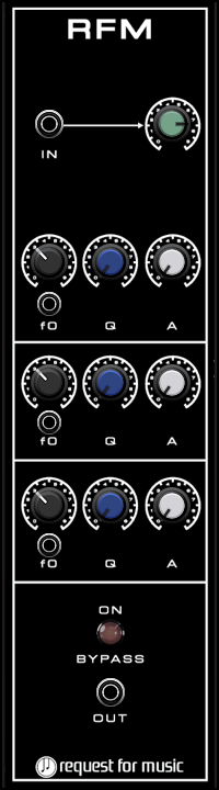
RFM-module
The RFM or Resonance Filter Module can be compared to a parametric equalizer.
It has three sections. Each section is a bandpass filter whose output is added on top of the original signal to add/amplify a chosen frequency band so as to give it a more distinct resonance on that set frequency.
The f0 knob sets the middle frequency of the band, while the Q-knob sets the ‘quality’ or resonance of that filter.
The higher the setting, the smaller the band.
The height of the band is set with the A (amplitude) knob.
The RFM-module becomes extra effective when trying to mimic instrumental sounds like strings or brass. Those instruments often have their own specific ‘resonance frequency’ (think of a violin or guitar for instance)
When you look up such a frequency and set that with the f0 knob and dial in Q- and A-settings, the sound should come closer to the original.
When creating original sounds RFM might help to make it sound more natural or just exaggerate some frequency to make the sound stand out more.
Below every f0-knob is an input to modulate that center frequency.
The input (top left) level is set with the green knob.
To have the RFM output its affected sound, the button needs to be switched on.
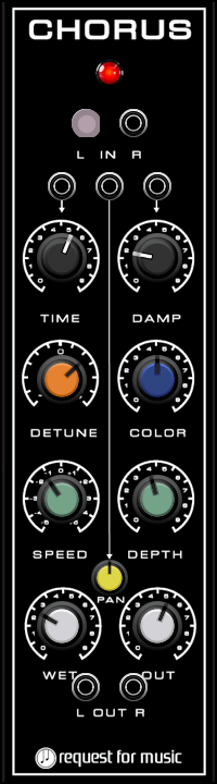
CHORUS-module
A chorus effect is mostly used to add an audible ‘doubling’ of tones.
It is a time modulation effect. TIME ranges from 30ms to 60ms and sets the basic time ‘displacement. DAMP sets an offset for a second sound from TIME.
DETUNE adds some FEEDBACK to the basic chorus sound, while COLOR allows you to filter the signal.
SPEED and DEPTH add modulation to the chorus basic signal, so to get a familiar CHORUS effect, set a speed of 1 and a depth of around 10.
Further there are external modulation inputs for TIME and DAMP.
The stereo output sends the signal depending of the WET and OUT knob settings.
The PAN knob decides where to put the signal over the stereo image and can be externally modulated.
Don’t forget to push the red button on top to switch the effect either On or Off.
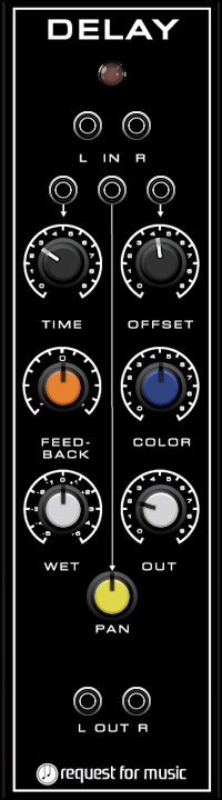
DELAY-module
A delay effect adds ‘bounces’ of a sound.
It is a time modulation effect. Higher TIME settings make it take longer for the bounce to be heard. OFFSET sets an offset for a second sound from TIME.
FEEDBACK defines how many bounces will be created from one signal, while COLOR allows you to filter the signal.
Further there are external modulation inputs for TIME and OFFSET.
The stereo output sends the signal depending of the WET and OUT knob settings.
The PAN knob decides where to put the signal over the stereo image and can be externally modulated.
Don’t forget to push the red button on top to switch the effect either On or Off.
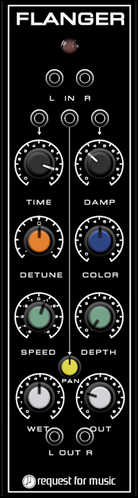
FLANGER-module
A flanger effect is closely related to a chorus effect.
It is a time modulation effect but with TIME ranging from 5ms to 20ms the sound is somewhere between phasing and chorus. DAMP sets an offset for a second sound from TIME.
DETUNE adds some FEEDBACK to the basic flanging sound, while COLOR allows you to filter the signal.
SPEED and DEPTH add modulation to the flanger basic signal – set the value for speed low and depth high to get a familiar flanging sound.
Further there are external modulation inputs for TIME and DAMP.
The stereo output sends the signal depending of the WET and OUT knob settings.
The PAN knob decides where to put the signal over the stereo image and can be externally modulated.
Don’t forget to push the red button on top to switch the effect either On or Off.
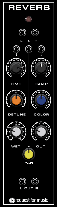
REVERB-module
A reverb effect is the ‘bread and butter’ effect to be used in most music
It can give the sense of depth of a small room up to the long reverb of a cave.
The TIME sets the length/decay of the Reverb, so higher settings to get that cave settings. The DAMP knob defines how much the reverb ‘tail’ is getting softer. The higher the value, the faster the tail is dampened in volume. To get real large cavernous sound, the TIME setting could be quite high while the DAMP setting could be pretty low. DETUNE adds some modulation into the reverb giving it some more depth, while COLOR allows you to filter the signal.
Further there are external modulation inputs for TIME and DAMP.
The stereo output sends the signal depending of the WET and OUT knob settings.
The PAN knob decides where to put the signal over the stereo image and can be externally modulated.
Don’t forget to push the red button on top to switch the effect either On or Off.
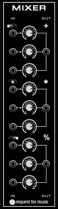
MIXER-module
The MIXER is meant to combine signals – it has 3 sections of 3 inputs to mix into 1 output each.
By combining a slow LFO triangle signal with for instance a faster square wave LFO signal you can create nice pitch modulation effects for a VCO.
Each section has a 3-way switch, that can change the MODE of mixing.
Standard mode is +.
In this case the signals are added.
Next mode is *.
Here signals are amplified. You can use this to create Ring Modulation by sending separate VCO signals to two inputs – use this to create bell sounds.
An other idea is to use an LFO medium fast triangle wave on one channel and use the Modulation Wheel signal on the other input.
This way the wheel decides how much ‘vibrato’ you can send to the PM connection of a VCO.
Last mode is %.
This is a mathematical function that only takes a signal in certain cases. This can lead to unpredictable signals when combining LFOs and Envelopes. You could even create whole new sounds when using VCOs as input and then send the output into a VCF.
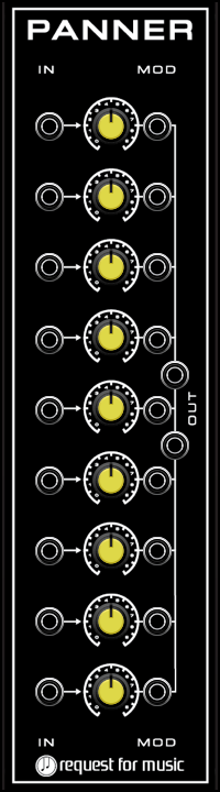
PANNER-module
When working with stereo modules like all effects and the COM module it might be nice being able to place the sound in the stereo field.
The Panner can help then. With inputs to receive nine signals, you can use the knobs to play them over the stereo field that is output on the main L and R outputs.
Every pan also has a MODulation input just to the right of each knob.
Send an LFO triangle wave to a MOD input to hear a stereo swirling sound.
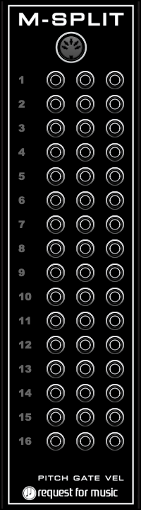
MIDISPLIT-module
Using MIDI instead of PITCH the Midi-splitter can be used to take signals from 16 outputs for PITCH, GATE and VELOCITY. Using Midi you have multiple channels to work with – each sending its own note information.
If you for instance use a master keyboard that can have a split keyboard set up, you can use one of the outputs for bass. and another to play a lead sound.
You can receive note, gate and velocity from a midi channel from the proper outputs.
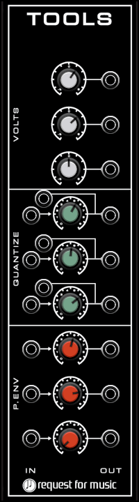
TOOLS-module
The TOOLS module combines some functions – VOLTS, QUANTIZE and P.ENV.
The top three outputs send the VOLTage between -5 and +5 Volts that you set with the knobs. This voltage can be used as a offset wherever needed.
Every of the three QUANTIZE section has a knob to set the quantize speed. This set the tempo at which to take a sample from the input.
That sample is then sent out to the output. If for instance you quantize a GLIDE output and send that to PM input of an oscillator you would get a stepped ‘glide’ instead of a fluent glide.
The speed can be set from 0 to 7500 Hz, meaning that could you also send a VCO output into the quantize in, to take a sample of the VCO’s wave and send that out as an ‘effected’ waveform.
Beware that if the quantize speed is low, you will get crackle effects instead of an audible note.
If, instead of setting a speed manually, you want to set the speed externally from for instance a sequencer, you can use the inputs that are situated slightly right and over the inputs.
P.ENV is a simple envelope with only a DECAY stage to set the length of. Left of the red knobs are three GATE inputs for the three envelopes. The outputs on the right send out the envelopes. Apart from using this as simple envelopes for VCF or VCA, you can also use this to ‘bend’ a note in from the start by connecting it to a PM input of a VCO. Set the modulation to a negative value to bend the note from the bottom up and set Decay on the P.Env and PM-depth as desired.
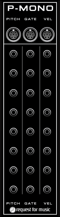
P-MONO-module
The P-MONOmodule allows you to use multiple VCO, VCF , ADSR, VCA combis to be used as polyphonic setup.
Connect a POLY source to PITCH, GATE and/or VEL to use upto 8 voice polyphony.
To that end there are 3 x 8 outputs where one PITCH, GATE and VEL make up for one voice.
Make sure to set the number of Voices in VM to max 8 to use this.
BLANK
A Blank plate is always helpful to use for extra visual speed in a setup, to keep ‘clusters’ apart.
Apart from that it also has a text-editor for keeping notes.
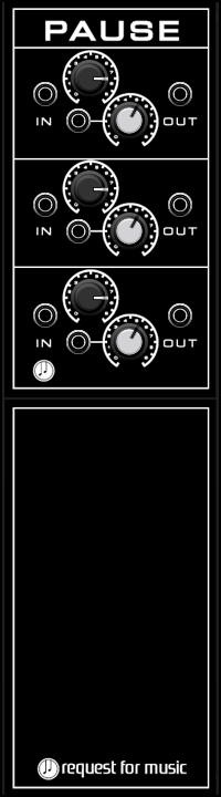
PAUSE
The PAUSE module contains 3 delays (not an echo though), that you can set from 0 to 10 seconds. The signal, coming in on the left, comes out delayed on the right side of the module and can have its level changed with the white knob.
You can use it with pitch, gate, sound or whatever you can think of that you want to output later..
You can even daisy-chain them to get longer delay times.
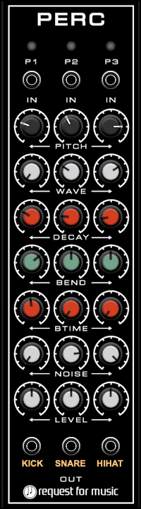
PERC
The PERC is a simple synthesizer percussion module, having 3 columns of knobs. Each column has PITCH, WAVE, DECAY, BEND, BTIME, NOISE and LEVEL.
PITCH sets the frequency of the note that is output when you send a GATE (or anything that can be used as trigger) on the top input of that column.
For P1 the pitch is set between 20 and 500 Hz.
P2 is set between 50 and 1500 Hz.
P3 is set between 100 and 7000 Hz.
P1 was intended for Kick-like sounds, P2 for snares and P3 for bells/cymbals, although nothing stops you from setting it all to just toms or whatever you like.
You can even click on the orange text at the bottom to give a column your own recognizable name.
WAVE mixes the sound between SINE wave and SAWTOOTH.
DECAY sets the length of the note.
BEND allows you to bend the note up or down in conjunction with BTIME.
Set the time for the note to bend with BTIME
Add NOISE to a sound for snares for instance.
LEVEL of course sets the output level from the bottom output per column.
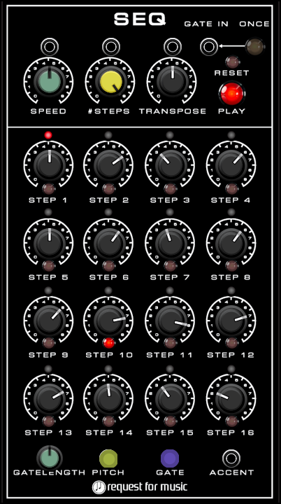
SEQ-module
With a sequencer you can create repeating patterns – you could use a sequencer to change the cutoff frequency of your filter on and on for instance.
Mostly it is however used to play looping melodies. For this you can set the step knobs to values from -24 to 24. Each step is a semi-tone. This means you have a range of 2 octaves down to 2 octaves up per step. If you want to play a C-scale, you would set the steps to: 0, 2, 4, 5, 7, 9, 11, 12.
In this case you would only need 8 of the available 16 steps. You can dial the yellow knob from 2 up to 16 for the amount of steps being played in the tempo set by the SPEED knob.
The TRANSPOSE knob allows you to give the melody an offset of -1 octave to +1 octave in semi-tone steps.
The outputs for PITCH and GATE send the set pitch and a gate out per step.
By SHIFT-CLICKING a step knob, you ‘de-activate’ the step so no pitch or gate is sent out, thus to silence the step or create a rest.
The PLAY button makes the sequence run, while RESET is a small button to reset the sequence.
The GATE INput lets the sequence jump to the next step depending on a trigger or gate entering this input.
If you however press the button to the right of that input, the sequence will play ONCE in the normal tempo as soon as any GATE is received…
An ACCENT output sends a gate for every STEP that has the button below the knob switched on.
You can use this to send an extra gate to get accents or use this to let a second sequencer go the next step by using the GATE INput to jump to steps using an external signal.
SPEED, STEPS and TRANSPOSE have inputs above them to modulate these.
Finally there’s a GATE LENGTH knob to set the length of the gate when output from the GATE output.
tip – when using multiple sequencers, set to speeds that are divisible, you can have slower and faster sequences running at the same time.
Use one for a slow bass at say 20, then use another at 4*20=80 to create 16th notes where the one running at 20 would be the quarter note.
make sure to save and reload the patch so that both sequencers start at the same point.
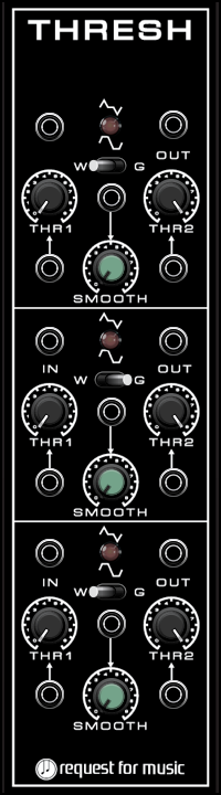
THRESH-module
The THRESH module contains three sections to set thresholds for a signal.
Every section has a INput and an OUTput.
Further it has two black knobs, the left one is normally used for a LOWER threshold and the right one for the UPPER threshold…
This means that when you input a triangle wave, you can cut off the lower part of the waveform by turning the lowers Threshold.
Obviously you can do the same for the upper part of the wave.
This will result in a different waveshape. You can use the green SMOOTH knob to indeed make the corners smoother.
You can use a LFO signal or even an audio signal to place thresholds on.
With audio signal you can not raise the smoothing to high or you will loose gain.
An other use might be INputting a sequencer signal and ‘filter’ out notes below or above a certain threshold.
And oh – for every use there is also a knob that lets you switch the output signal BETWEEN the tresholds or OUTSIDE of the thresholds.
and one more thing is that below the previous mentioned switch is a W and G labelled switch.
Set to W it behaves like explained before.. set to G however, the output is a gate signal…
This should make for extra fun playing around with wave shapes in the F_SYN bundle!
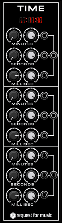
TIME-module
If for any reason, you need a gate to happen at a specific time-interval, TIME is your module!
Except for giving you feedback of the current time, it has three sections.
Each of the sections has a MINUTES, SECONDS and MILLISEC knob.
MINUTES and SECONDS can be set from 0 – 59 and MILLISEC can be set from 50 – 1000.
To the right of that black knob you’ll find a white knob that sets the GATETIME from 0.05 – 0.95 x the set time.
The output right to the knobs sends a GATE at the set time-interval.
Per MINUTES, SECONDS and MILLISEC there is one output that sends the total of all these set time-intervals in one GATE – so i f you have set SECONDS to 2 and MILLISEC to 500, that output will send a GATE after 2 and a half seconds.
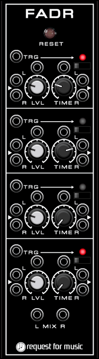
FADR-module
F_FADR is a 4 channel fader module intended for use with generative music.
Each stereo channel has Left and Right in- and outputs, with volume control up to 2 x the input level.
The TRG input starts or stops a FADE-cycle.
The FADE-time i set in seconds with the TIME knob.
So if TIME is at set at 2 and the TRG input receives a gate, the attached input signal FADEs in over 2 seconds.
If the TRG input receives a new gate signal, the output FADEs out to 0 over 2 seconds again.
A 3-way switch can change the Time knob range between: 0-60 seconds, 1 – 10 minutes, 10 – 30 minutes.
All 4 outputs have a combined MIX Left and Right output.
The RESET button on top resets all FADE states to false, meaning there is no output and triggering can start.
At initialization of the module this happens automatically of course, but in case a state for a channel gets stuck, you can reset this.
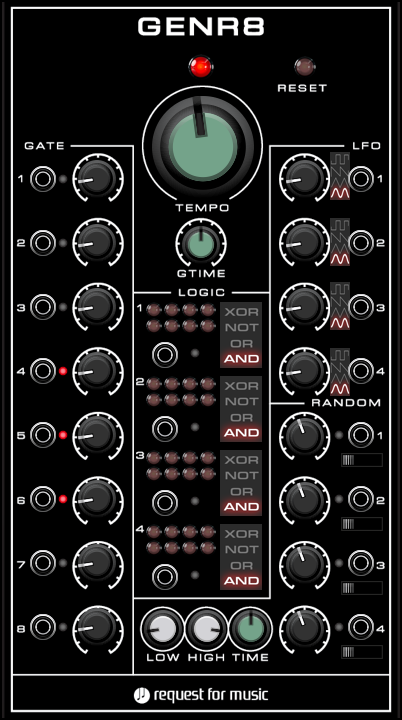
GENR8-module
GENR8 is a module aimed at creating generative music.
It is created using input of Rolf Kasten, who has just released an epub on that subject for Voltage Modular.
Everything in GENR8 is based on the Master Clock, the big knob you can not really miss.
This sets the time for a repeating pulse, from once every half hour, yes once every HALF HOUR, upto 120 bpm.
From 10 BPM ( or once every 6 seconds) up to 120 shows as BPM, below 10 the value is shown in seconds.
If you right-click Edit Value the knob, you have options…
Just fill in a value and it will be transferred to BPM, fill in 10s and the knob is set to 10 seconds so you get a pulse every 10 seconds…
Fill in 10m and it is calculated from minutes to seconds, so the knob is set at 600 seconds.
Below this Master Clock you can set a gate time, so how long the gate is ‘opened’.
Further there are 4 sections.
On the left you’ll find the **GATE** section.
Here are 8 outputs that send a clock depending on the setting of the knob. With the knob you can go from 1/16, 1/12, 1/8… 14, 15, 16 times the setting od the Master Clock.
So – with the default setting of 10 BPM, you have a range to send gates from 0.375 seconds up to 96.0 seconds for a gate to repeat.
With the Master Clock at its lowest setting you can go from 112.5 up to 28800 seconds (8 hours!)
Each of those 8 outputs can have their own settings so a lot of events that you can start this way.
If that is not enough there is a **LOGIC** section in the middle.
There you will find 4 outputs with 8 led-switches and a slider that you can set to AND, OR, NOT or XOR.
If you switch on a LED, the module keeps track of he numbered GATE output port. The LEDs go from 1, 2, 3, 4 from left to right and 5, 6, 7, 8 on the row immediately below.
That goes for each of the 4 LOGIC combinations.
If you switch 1 and 3 on, the module looks at the output GATE values from gates 1 and 3, and then uses a LOGIC function output a gate value.
When set to AND there will be output when 1 AND 3 overlap.
When set to OR there will be output when 1 OR 3 is ‘high’
When set to NOT there will be an output when NEITHER 1 OR 3 has output
When set to XOR there will be output when 1 and 3 DO NOT have output.
Then the **LFO** section.
The LFO section has 4 LFOs that are linked to the Master Clock as well, meaning that with a setting of 1 of the knob, the frequency will be 10 BPM = 10 beats per minute = a beat every 6 seconds, so 1/6 Hz. With the range of 1/16 up to 16 x that would be a frequency of 2.667 Hz up to 0.01042 Hz, let alone if you dial the Master Clockl is set at its slowest rate.where with a setting of 16 a cycle of the LFO would last 8 hours.
Finally there is a **RANDOM** section.
Here are 4 outputs that send a GATE out. The knob sets how many GATEs with the same randomly chosen time will be output.
In the middle part of the module on the bottom there are a LOW, HIGH and TIME knob.
LOW and HIGH set the range where a RANDOM value is chosen by the module.
That random value ios picked in such a way that it still is in line with the overall clock.
Time sets the GATE open time for the random GATE.
All in all this module can be used as a master controller in a generative system running sequencers or driving ADSRs at random within a set clock range or at such a low speed that repetition is hardly noticeable.
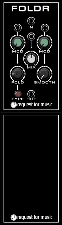
FOLDR-module
F_FOLDR is a so called Wavefolder that takes a signal and flips the signal above a certain threshold.
The louder the input signal, the more the folding begins to occur.
The number of ‘FOLDS’ can be set with a knob.
Further there is a SMOOTH knob to smooth the signal if needed.
For both FOLD and SMOOTH there is also a modulation input and knob to set modulation amount.
The central MIX knob lets you mix between the original input signal and the folded signal and can be modulated.
The TYPE switch lets you choose between two types of Folding output.
The F_FOLDRx2 has two of these modules in one to save space if needed